Assembly Instructions
Introduction
The heart of the FHTbot is an ESP8266 micro-controller. A micro-controller can be considered a miniature single chip computer.
Thank you to Flinders University, Hackerspace Adelaide and PCB Way. The FHTBot wouldn’t be possible without their generous contributions.
Please take a moment to explore their products, activities and services:
• Flinders University http://flinders.edu.au/
• Hackerspace Adelaide http://hackerspace-adelaide.org.au/
• PCB Way http://www.pcbway.com/
Be Careful
Don’t do screws up too tight.
Don’t use too much force, ask for help.
Check that wires are connected correctly.
Make sure the battery box is turned off when connecting to USB.
All parts
Here is a pdf document containing a picture of all the parts in the kit and their names. parts.pdf
Steps to build your FHTbot
- Identify all the parts in your kit against the picture.
- Undo all of the screws on the back of the Main Board using the small flat blade screwdriver.
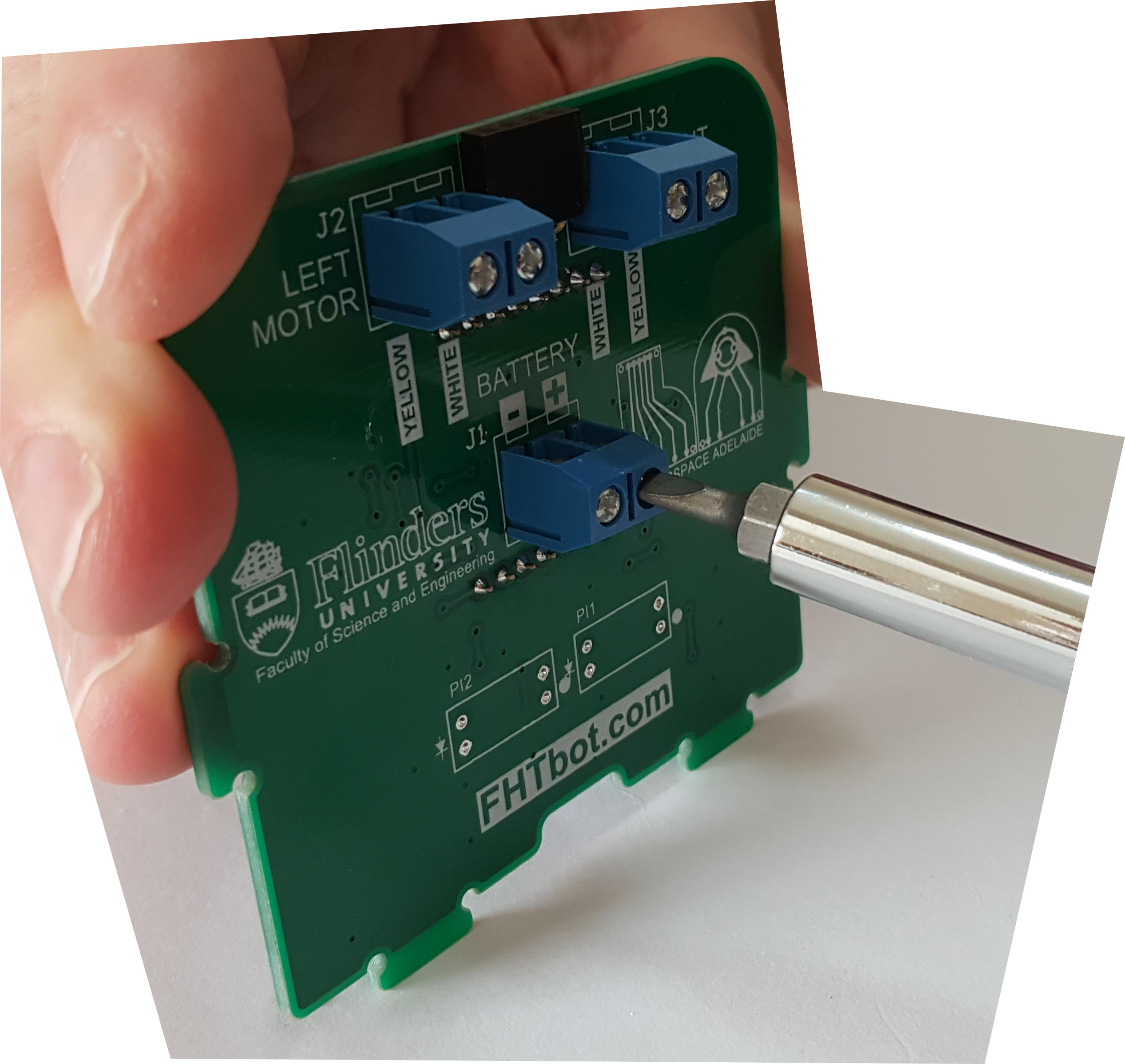
- Screw the Battery Box wires in place using the small flat blade screwdriver. Red = + Black = –
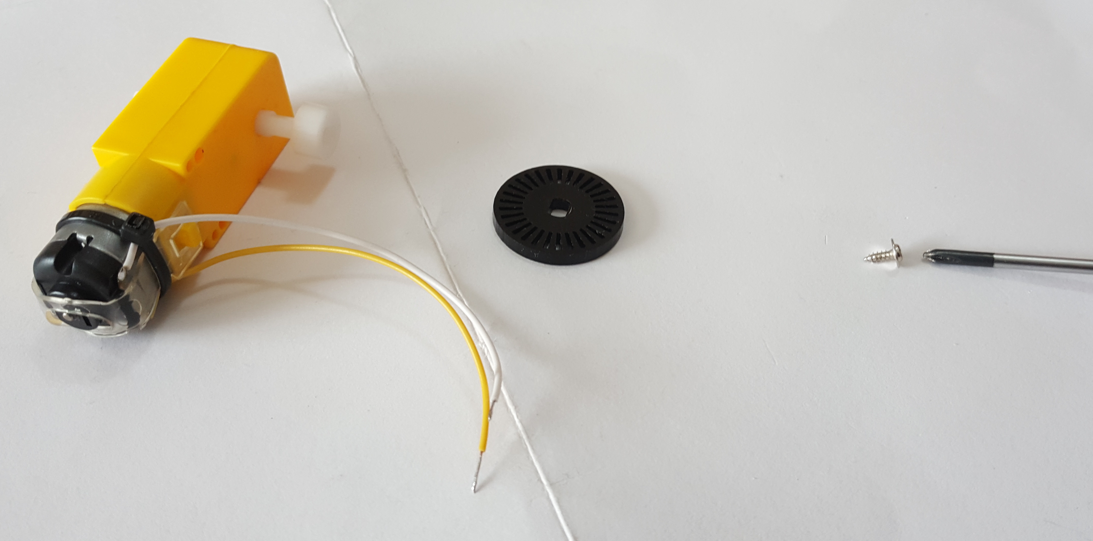
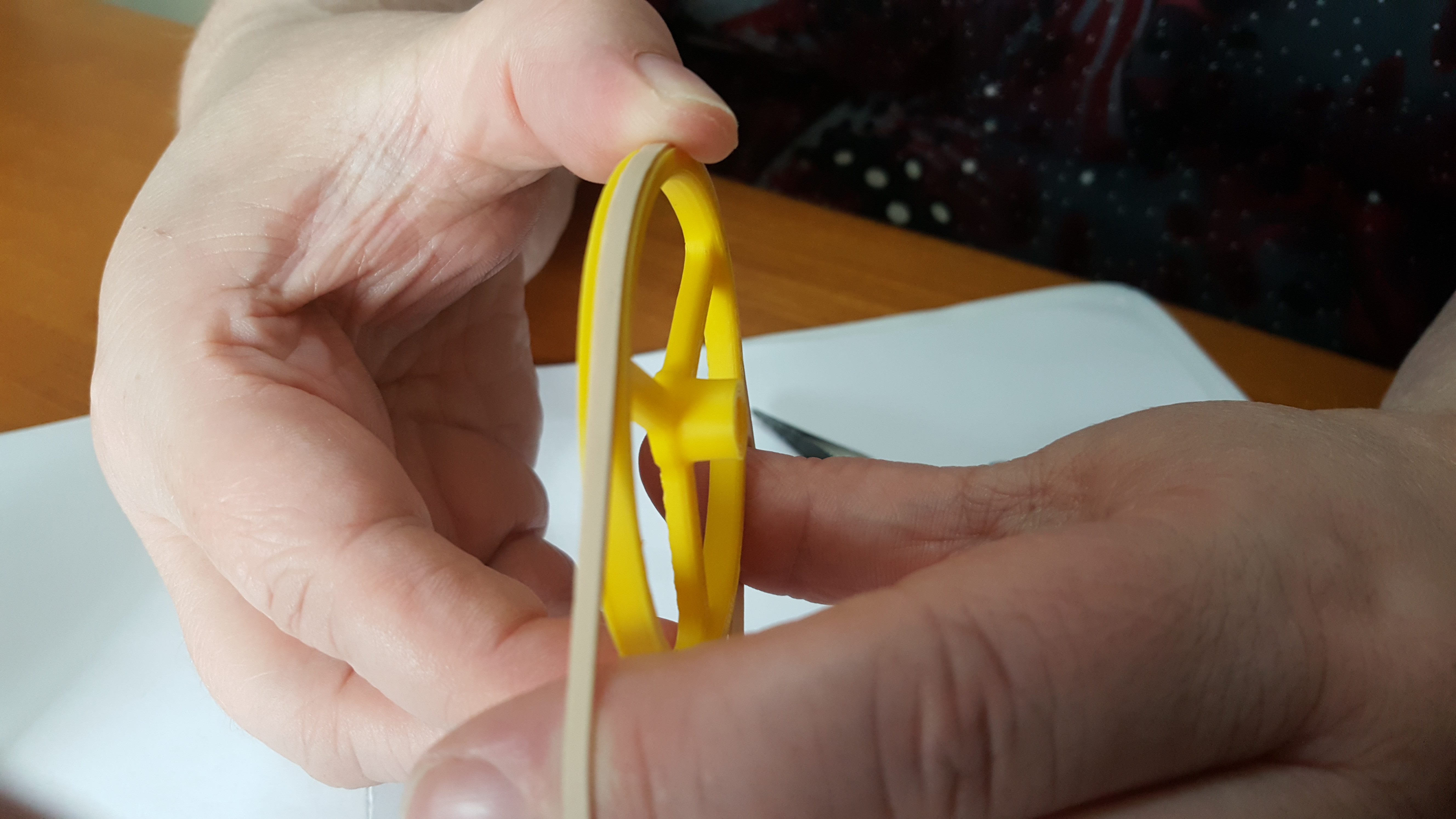
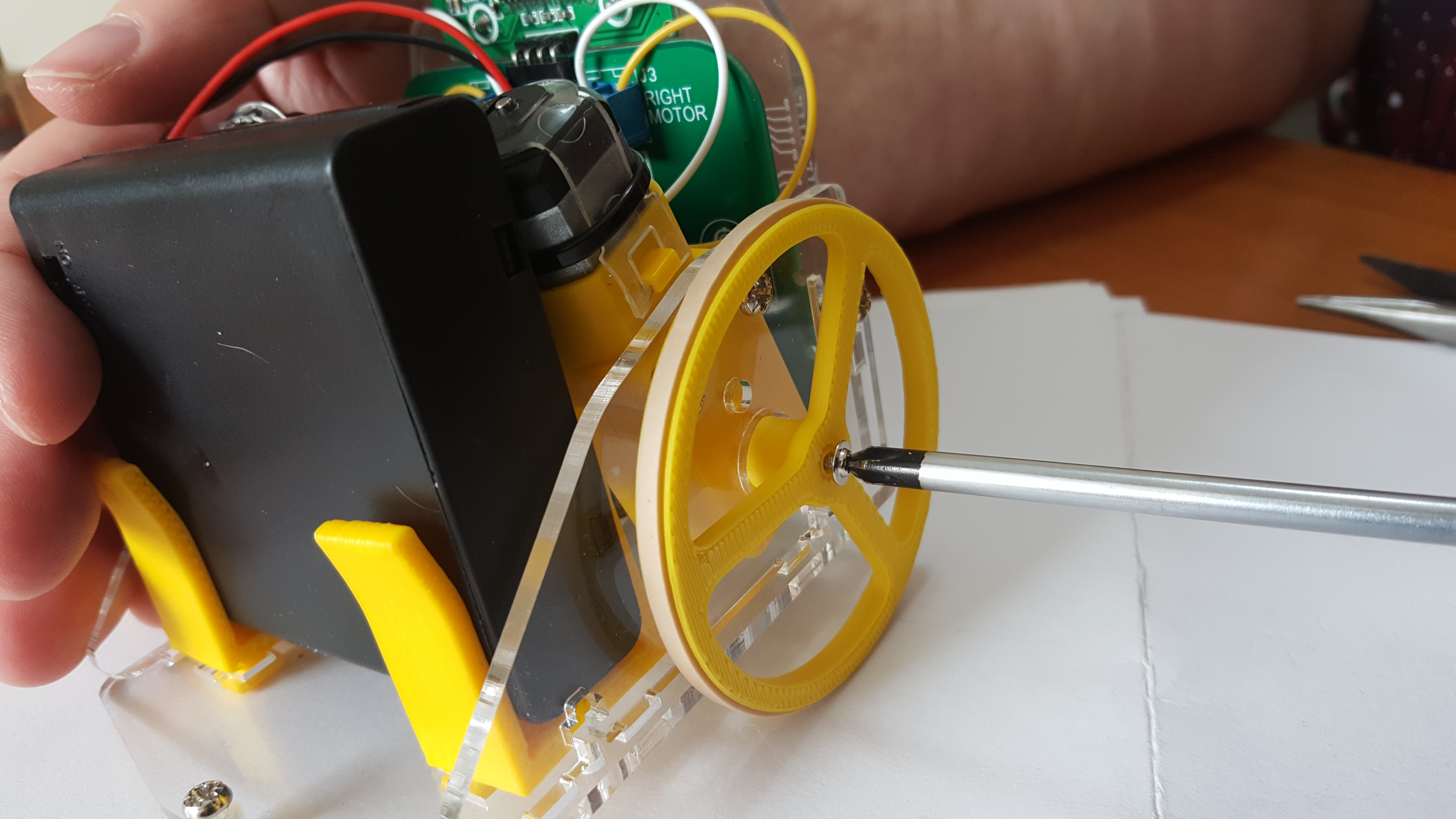
- Put the Spacer on the motor shaft on the same side as the wires. Then place the Encoder Wheel on top of the Spacer. Screw these together using one of the Motor screws and the small phillips head screwdriver.
- Be careful not to use too much pressure as acrylic is brittle. Ask for help if you need it.
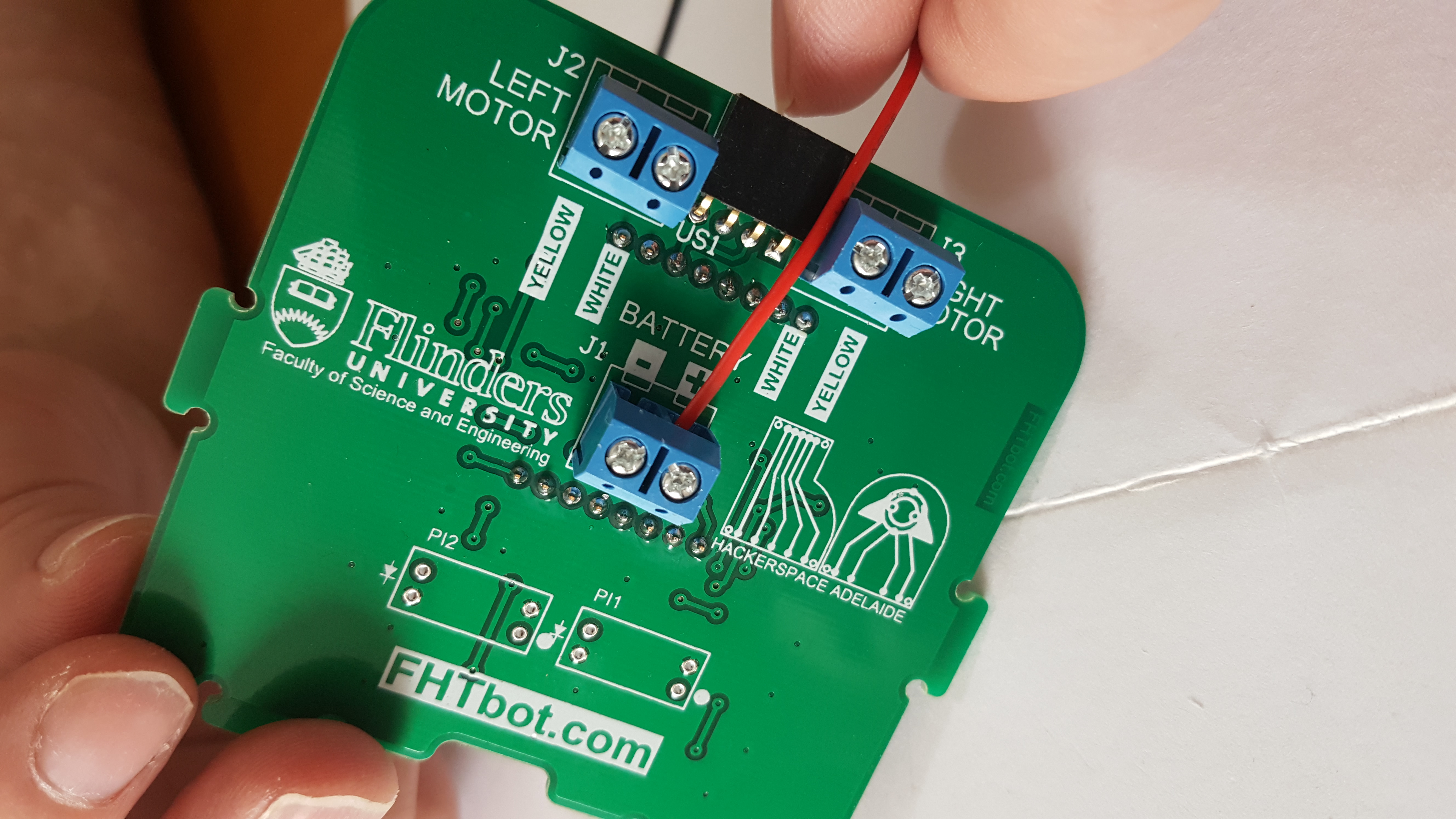
- Screw the left Motor in place on the Main Board using the flat blade screwdriver, match the wire colour to the writing on the Main Board.
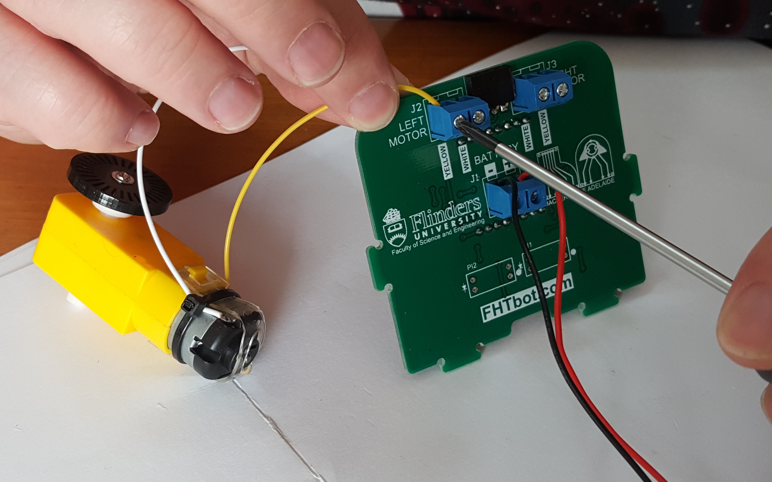
- Do the same for the right Motor.
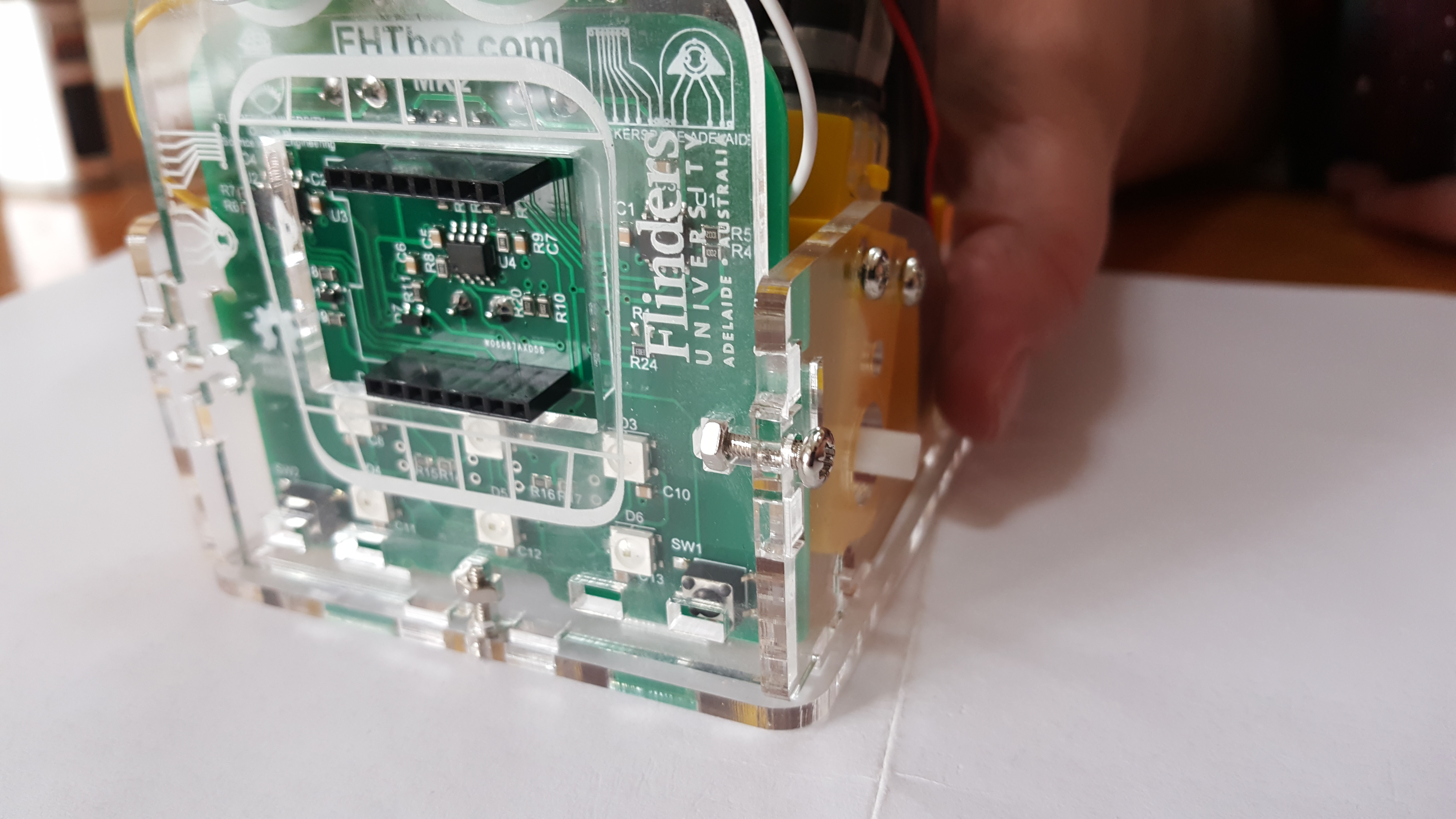
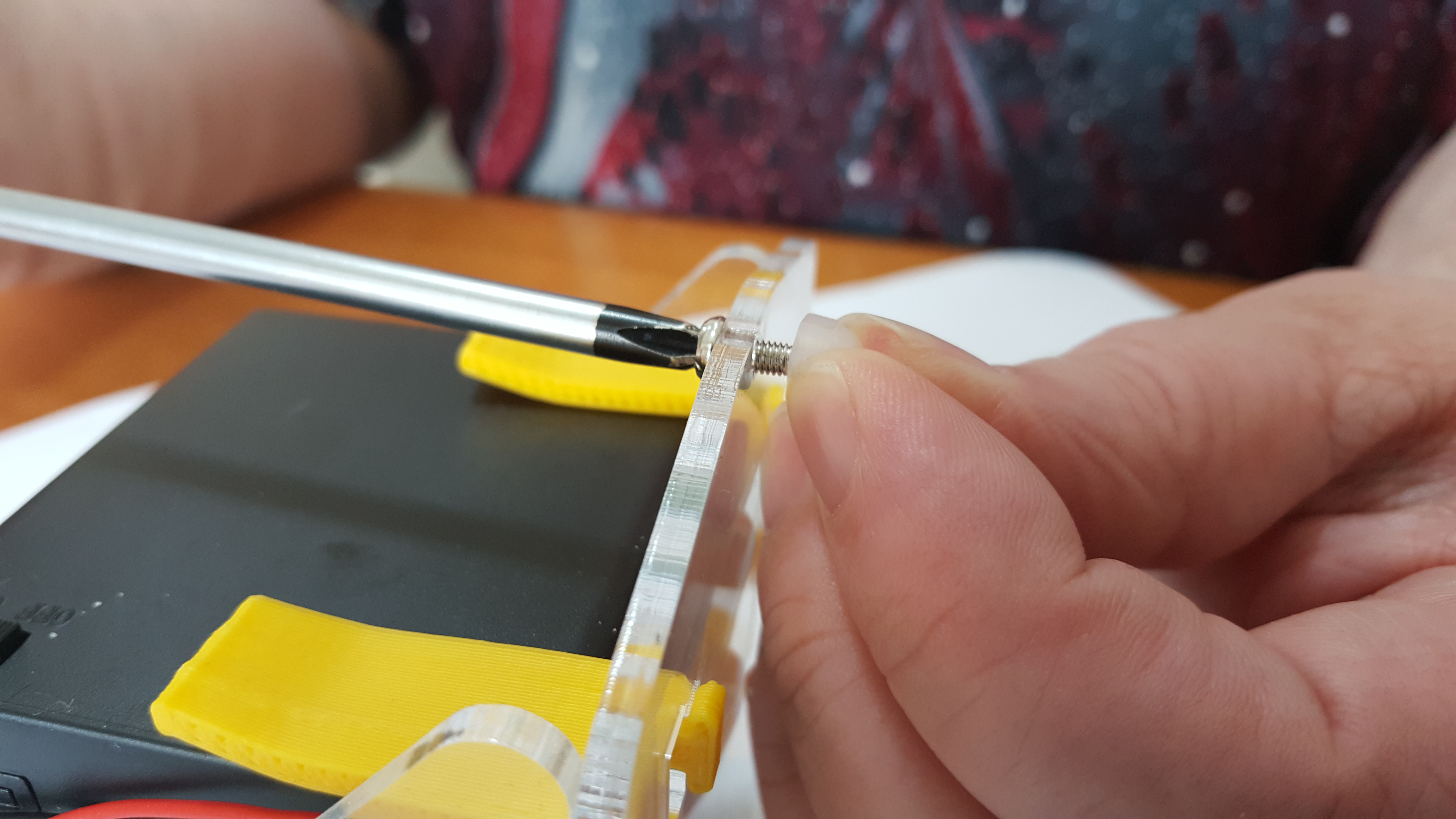
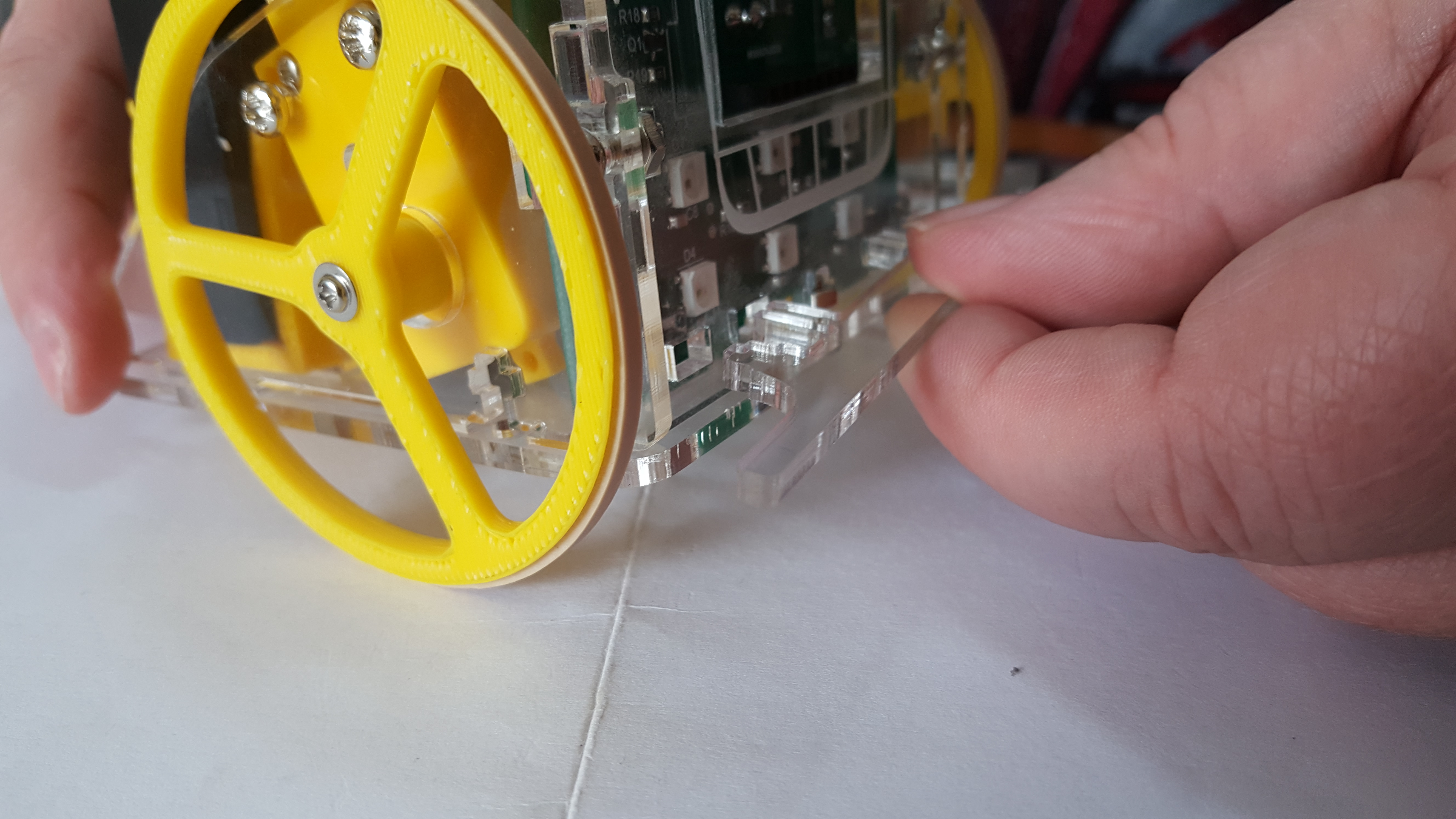
- Screw the motors to the Side Panels using a Long Screw and a large phillips head screwdriver. Make sure that the solder terminals are facing inwards.
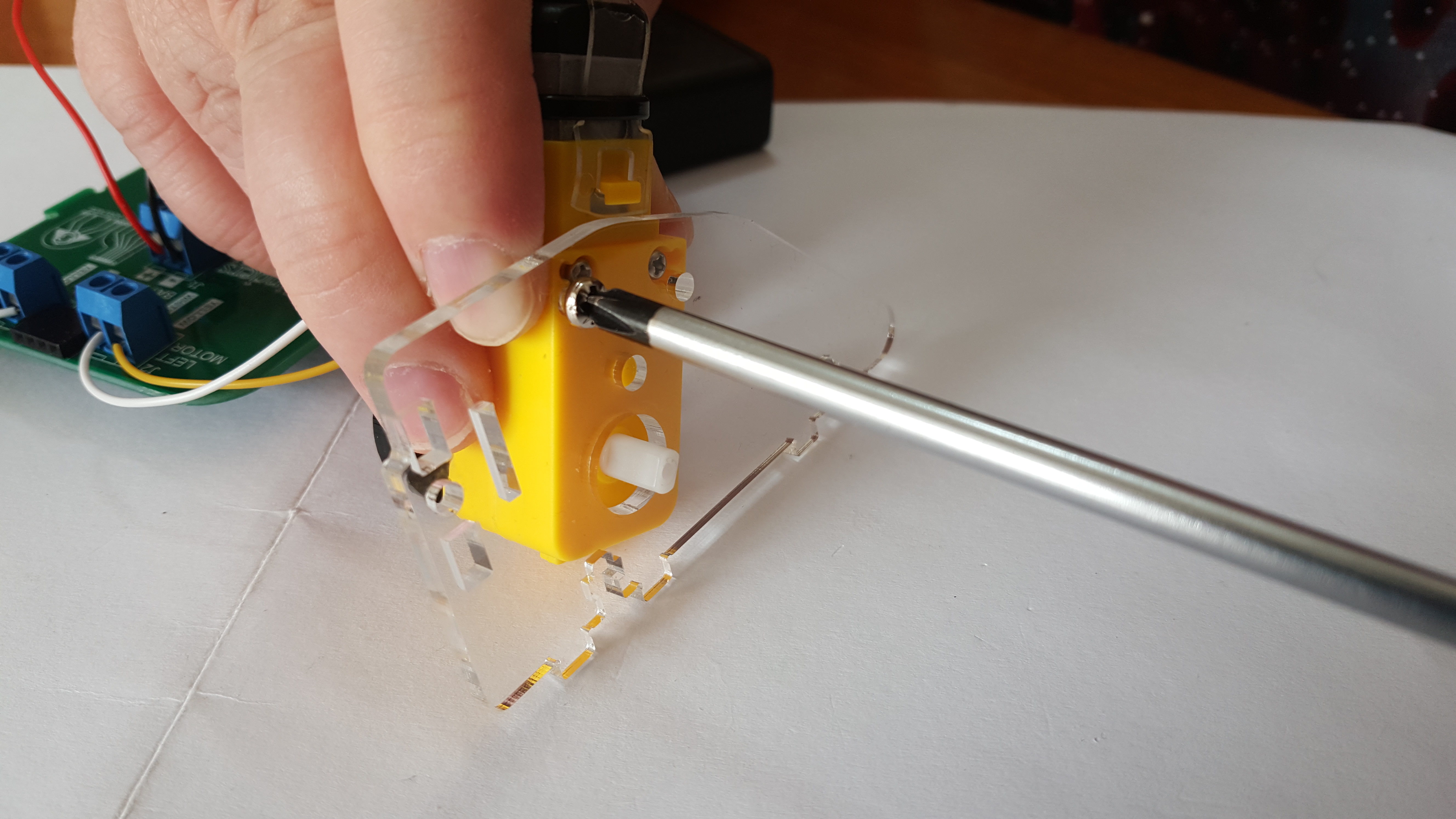
- Do the same for the other motor.
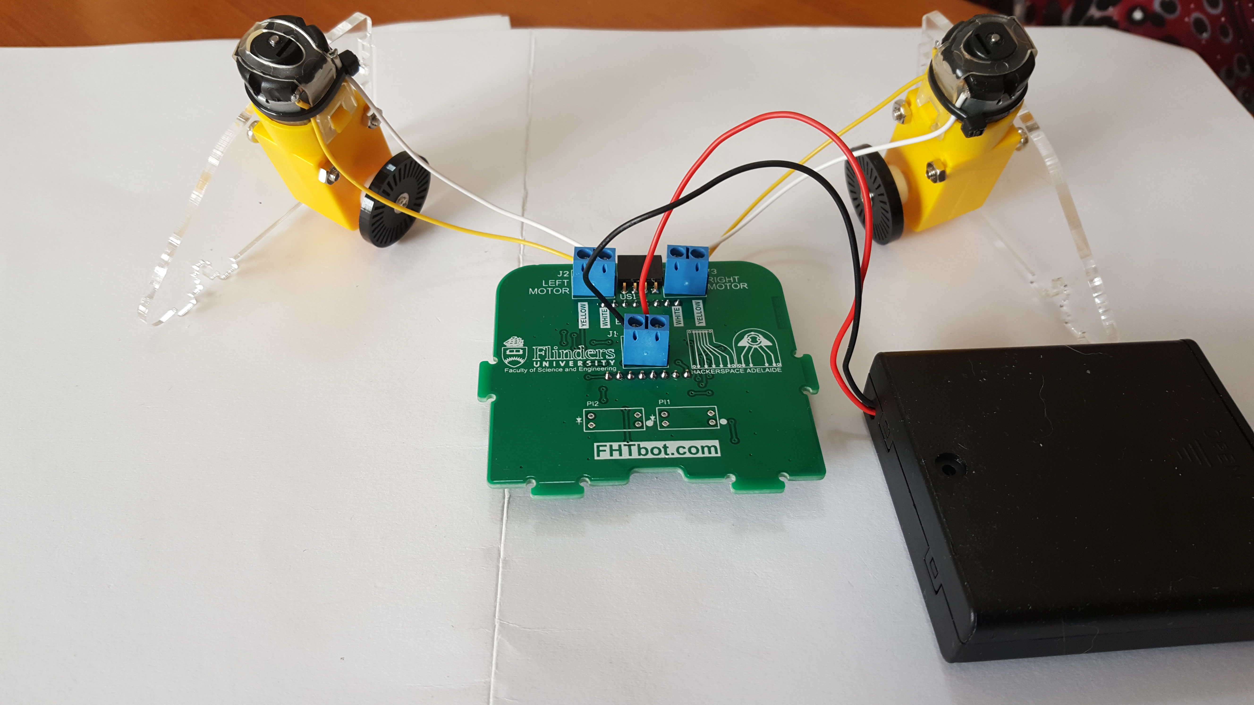
- This is what you should have now.
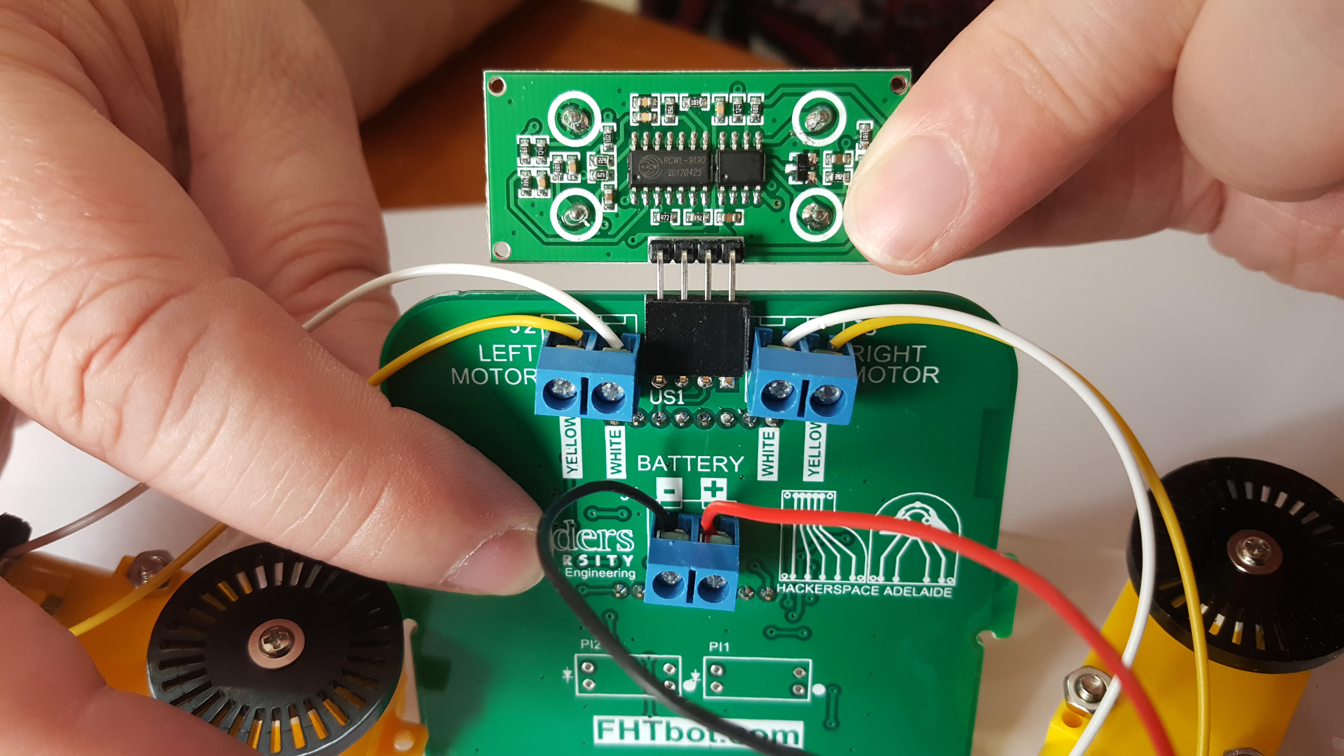
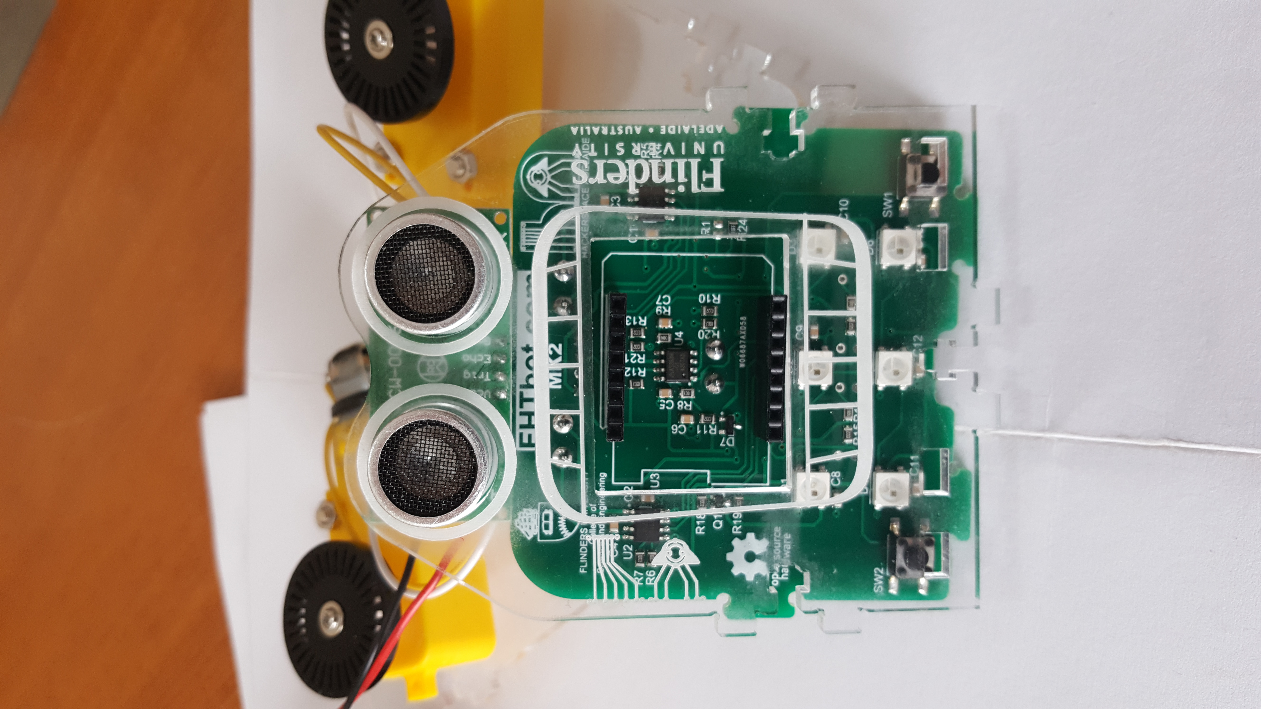
- Gently press the Sensor into the socket at the top of the Main Board.
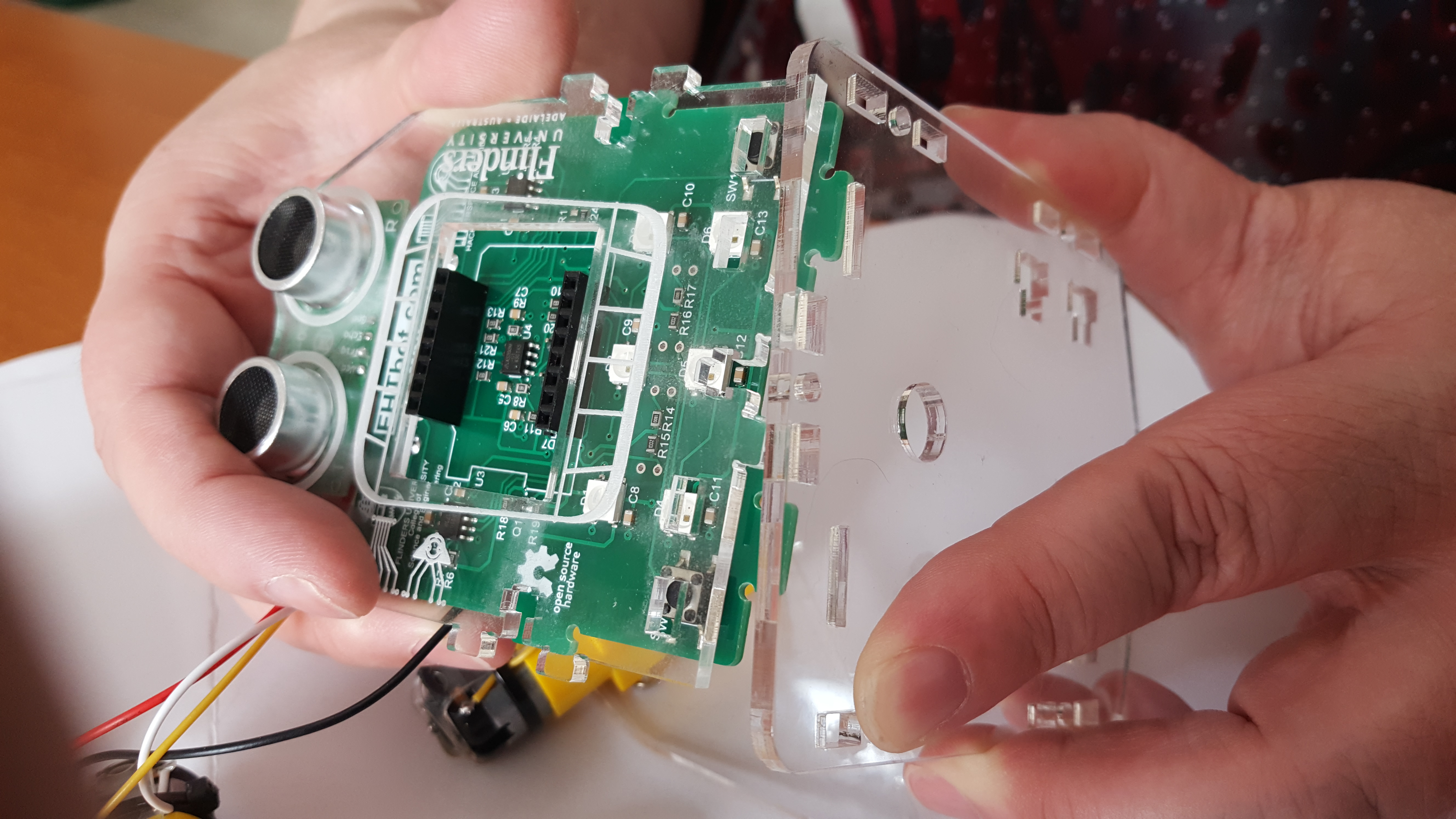
- Align the Front Panel with the Main Board.
- Align the Front Panel and Main Board with the Base.
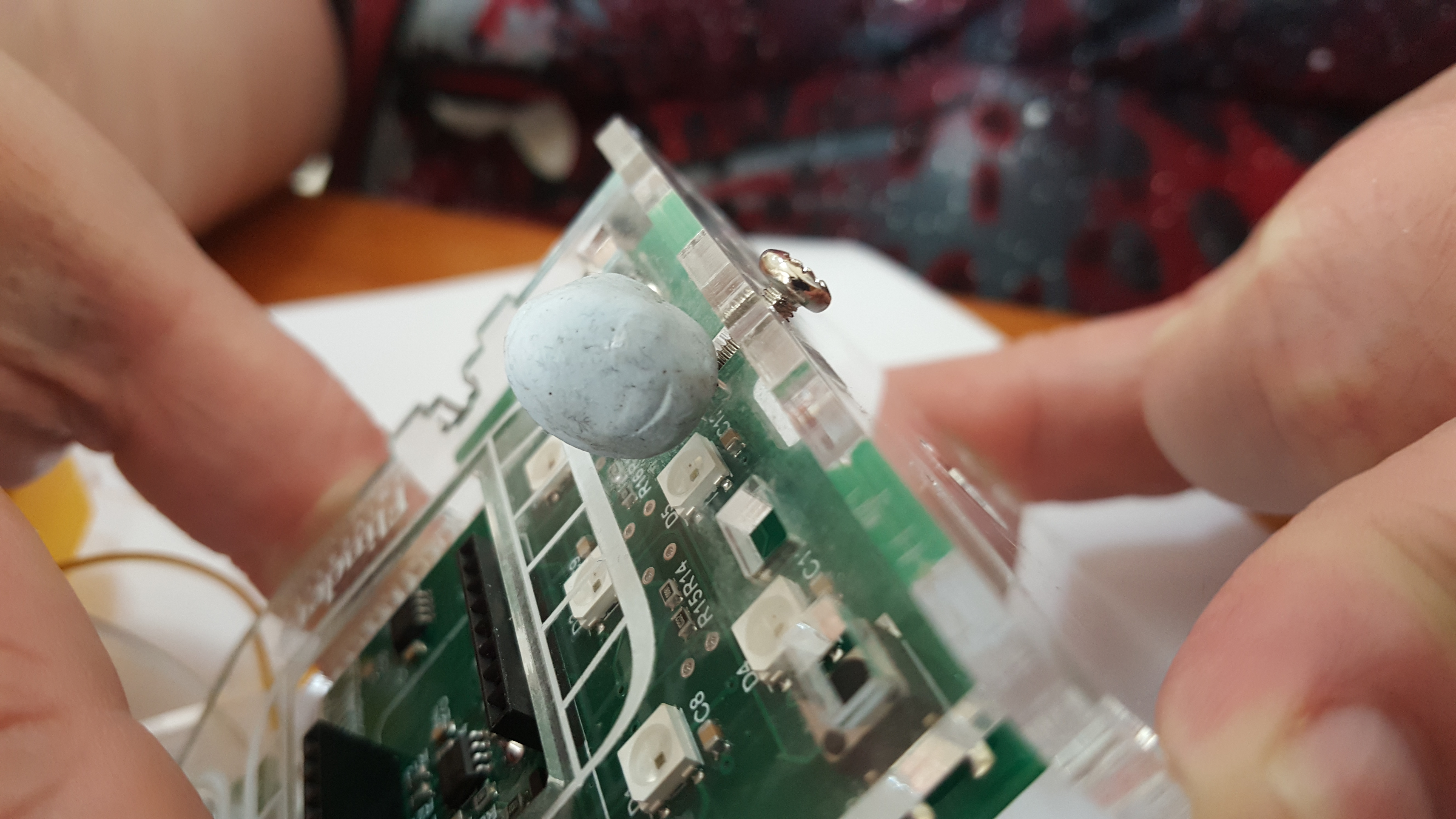
- While supporting the nut with a piece of blu-tac insert a Medium Screw and tighten with the large phillips head screwdriver.
- Insert both Battery Holders in the Base and slide towards the centre.
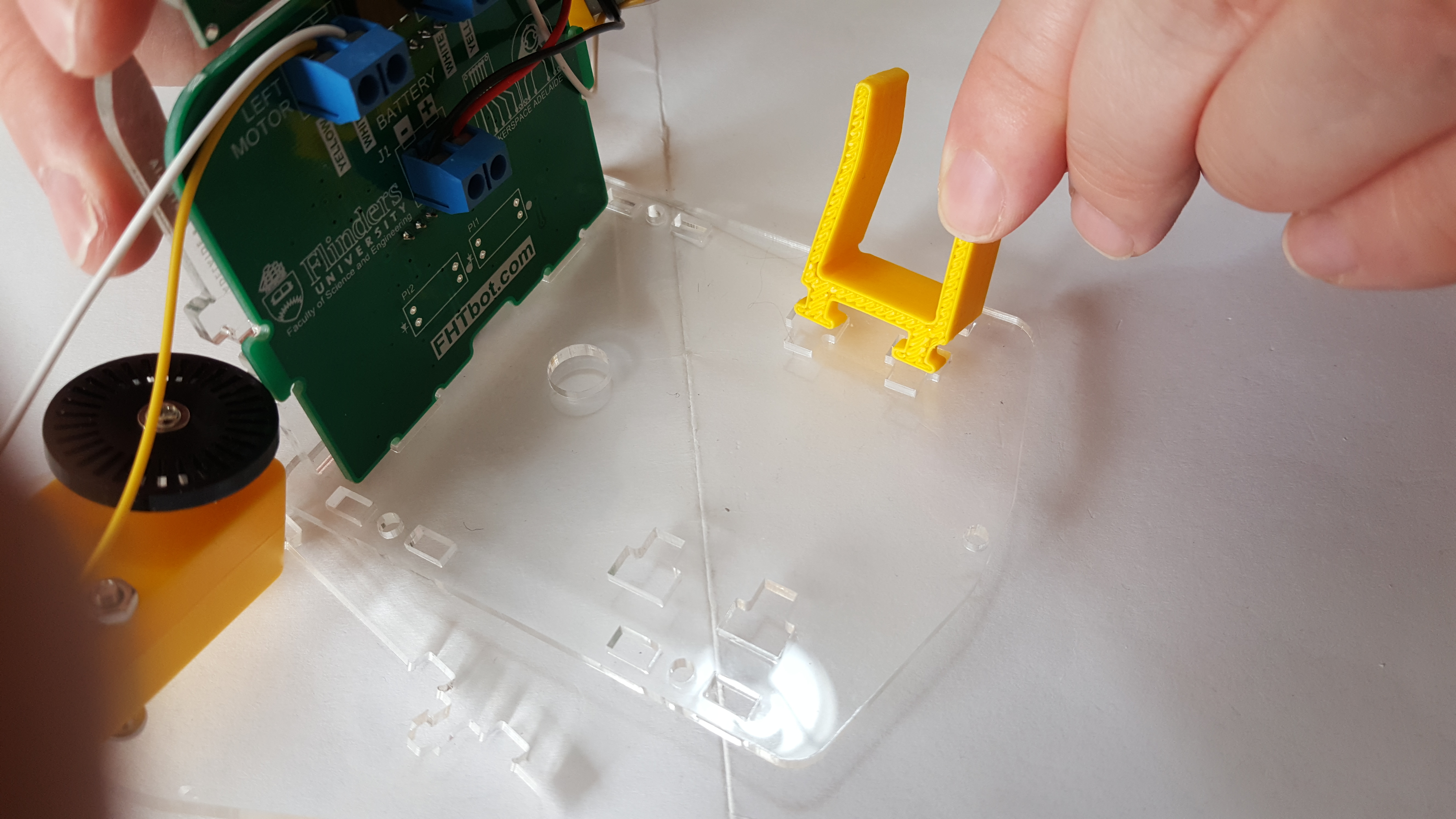
- Insert both Side Panels into the Base being careful to line up the Encoder Wheels and the Front Panel.
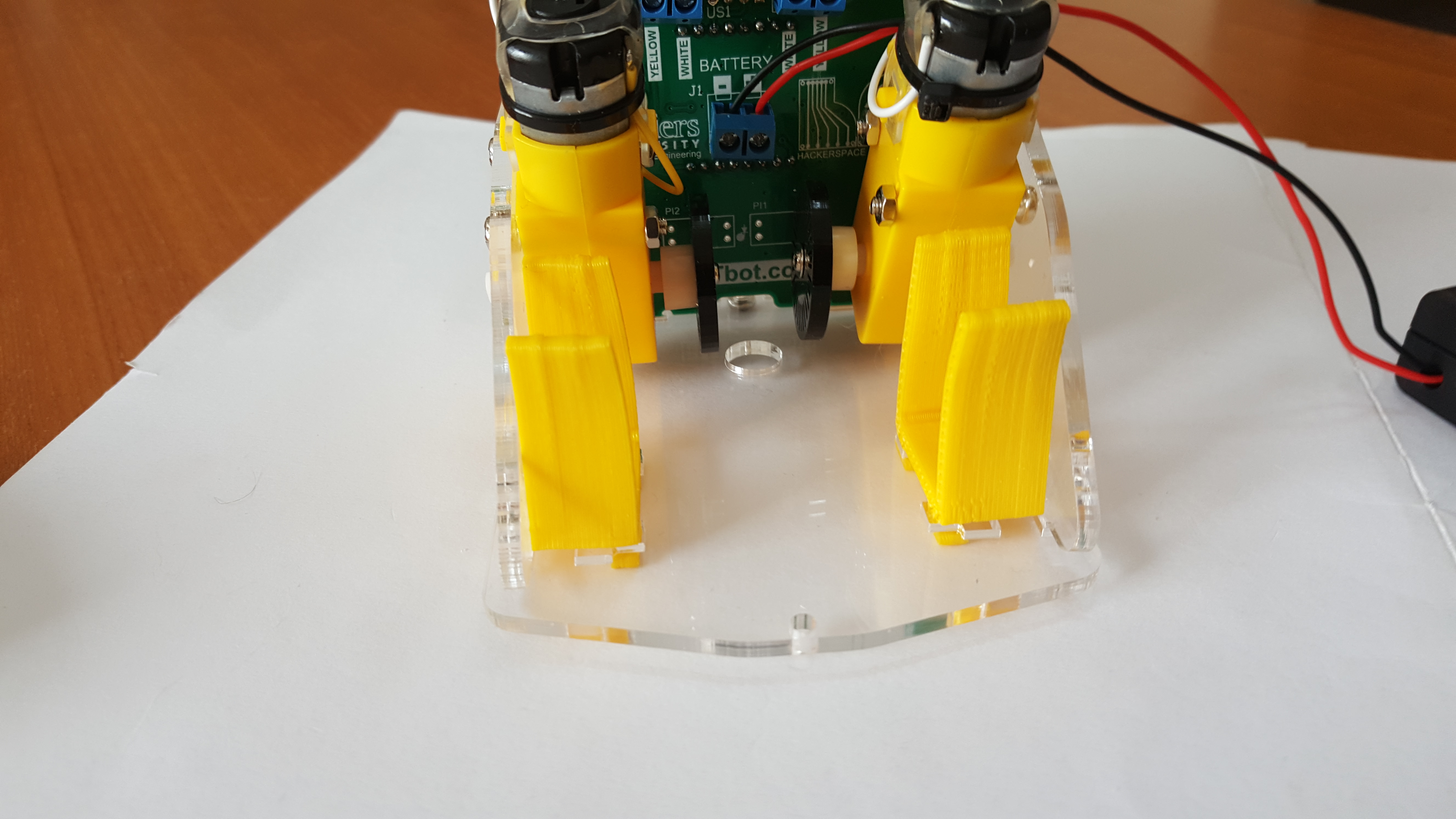
- Make sure the Main Board is in the slots of the Side Panels.
- Screw the Side Panels to the Front Panel and the Base, this will use the remainder of the Medium Screws.
- Screw the Foot onto the back of the Base with a Small Screw and a large phillips head screwdriver.
- Put the Tyres on the Wheels and screw the Wheels onto the FHTbot using the remaining Motor Screws and the small phillips head screwdriver.
- Insert the bumper into the Front Panel of the FHTbot.
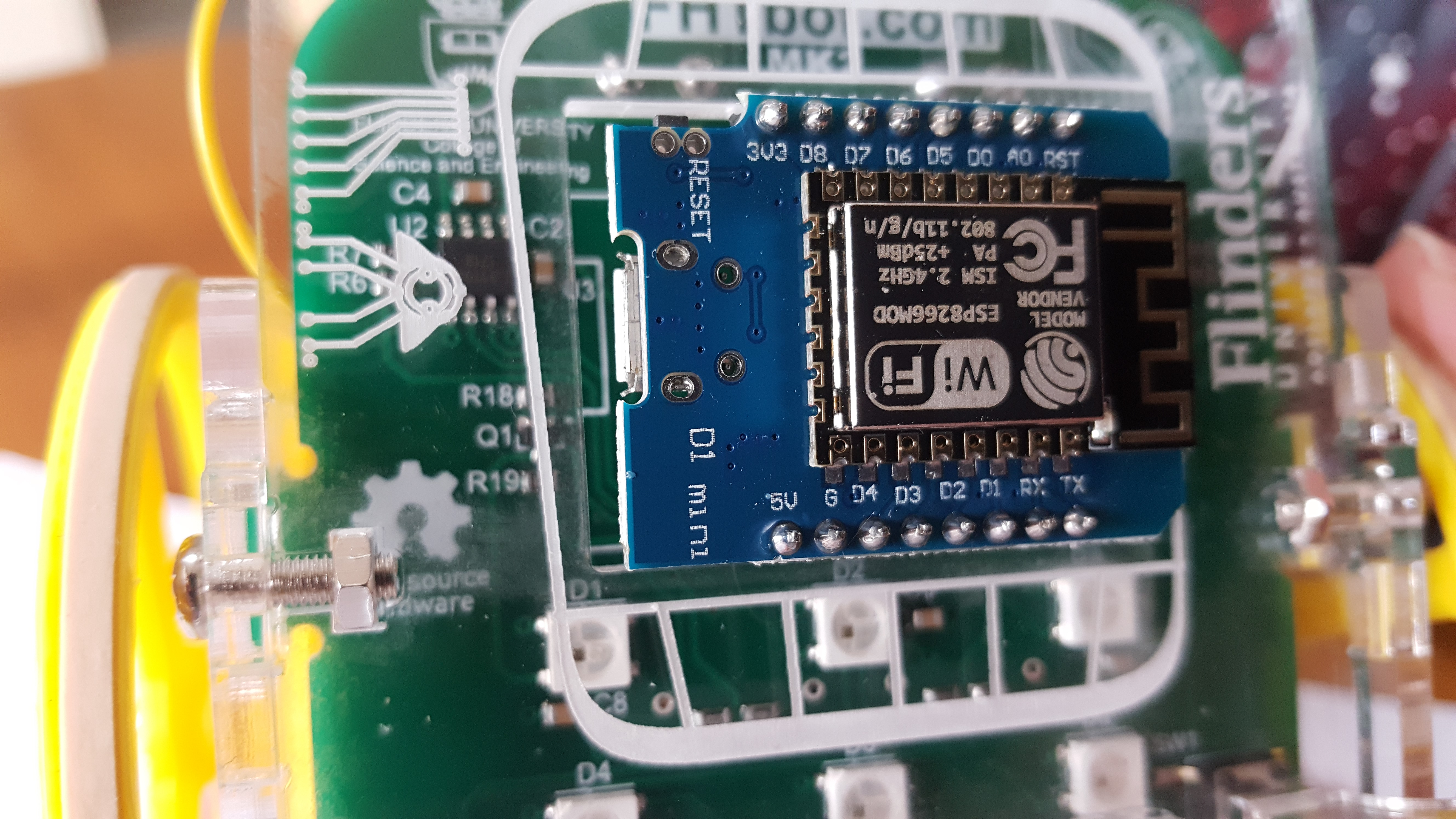
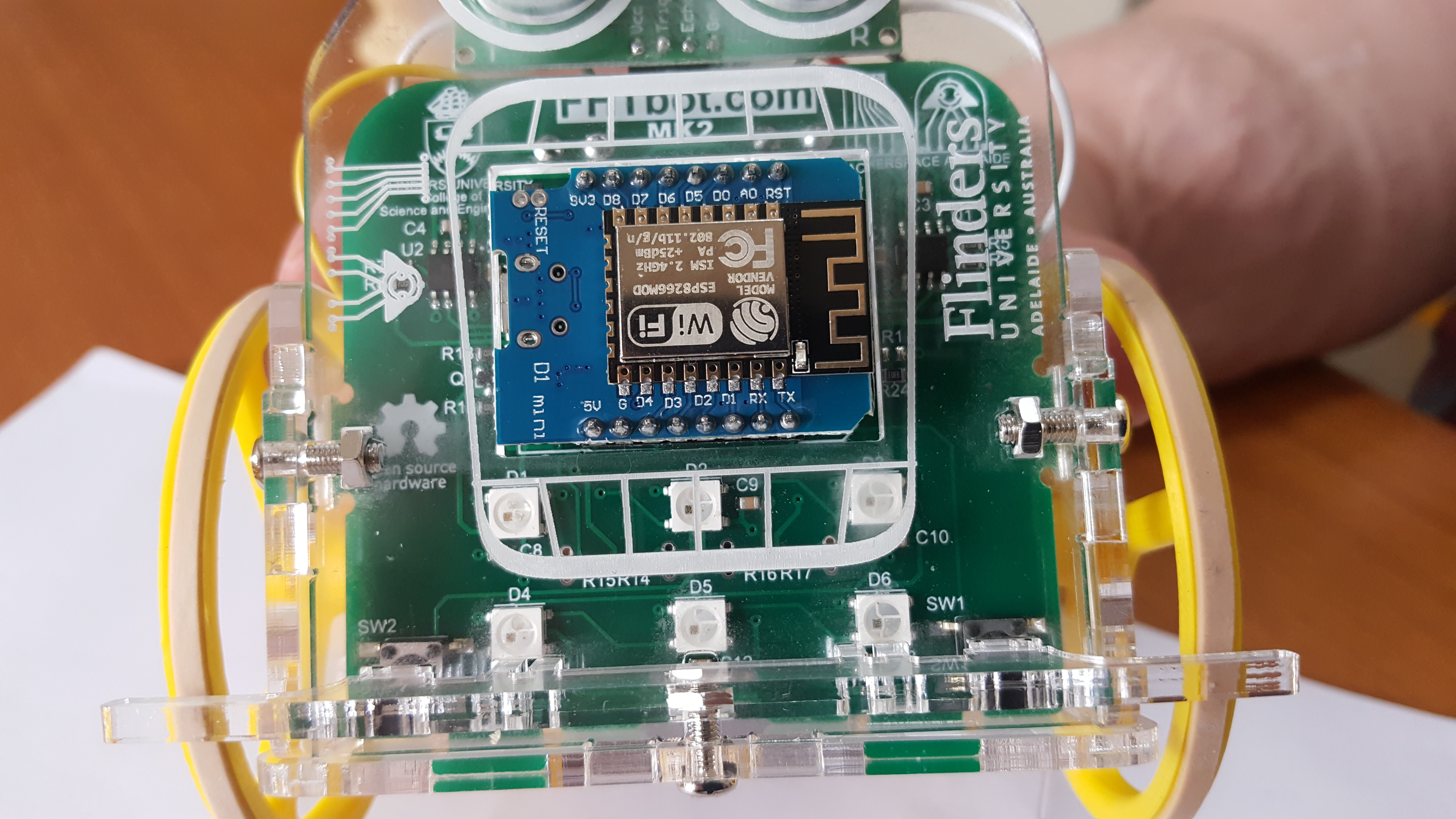
- Insert the Micro Processor, lining up the USB socket with the notch drawn on the Main Board.
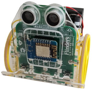
- This is how your FHTbot should look.
- Get your FHTbot checked over and then insert batteries and turn on the switch on the Battery Box.